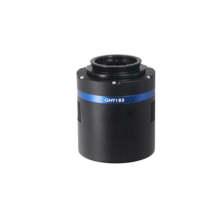
QHY 183M Cooled Monochrome CMOS Telescope Camera
- Anti-dew heater to eliminate condensation and ice buildup
- Anti-amp glow circuit to reduce long exposure amp glow
- 128 MB DDR memory to speed up download times
【Cocoon Nebula】
By Simon Todd, with QHY183M
QHY183 is a model designed for astrophotography beginners. It exhibits excellent sensitivity and low noise, with the back illuminated 183 having higher sensitivity and somewhat higher resolution. It is well suited to planetary and deep-space imaging particularly when mated with the CFW3 filter wheel. This model has two-stage thermal electric cooling of the sensor to about minus 40 degrees C below ambient for maximum reduction of dark current noise in long exposures.
QHY183 incorporates QHY’s Anti-Amp Glow technology to significantly reduce typical CMOS amplifier glow to a minimum, allowing excellent calibration by subtracting a dark frame.
QHY183 utilizes the Anti-Dew features common to the QHY COLDMOS cameras. Dew is moisture that condenses from the air onto the outside of the chamber window. Frost is water vapor that freezes when it comes into contact with the inside of the chamber window or the surface of the sensor. QHY has nearly 20 years of experience designing cooled cameras and these models benefit from those years of anti-dew and anti-frost design experience. To help prevent dew from forming on the chamber window heating elements are built into the light shield just above the chamber. To avoid frost from forming inside the chamber a desiccant tube is provided that can easily be attached by the user to the outside of the camera when needed to dry the internal atmosphere of the chamber and remove any built-up moisture.
QHY183 models can be used as guiding devices, too. The opto-isolated guiding port is a standard ST-4 configuration using an RJ11 style Jack. A guiding cable is included with each camera.
The 183 with its smaller higher resolution sensor is a good match to short focal length telescopes or for imaging smaller dim objects through a large scope. The larger 163 gives a greater field of view and would be a good choice for imaging larger areas of the sky such as nebula or when coupled to a longer focal length telescope to take greater advantage of the scopes full field.
The QHY183M is a one-inch, 20 Megapixel back-illuminated monochrome CMOS camera with a peak QE of 84%. The pixel size is 2.4um, yielding high-resolution with modest size telescopes. The camera is capable of producing 15FPS@20 Megapixels. It has a two-stage TEC that cools the sensor to -40C to -45C below ambient. The ADC is 12-bit / 16-bit with 1e- read noise! The computer interface is USB 3.0 and exposure times can be set from 50us to 3600sec.
Model | QHY183M/C |
CMOS Sensor | SONY IMX183 BSI CMOS |
Mono/Color | Both |
FSI/BSI | BSI |
Pixel Size | 2.4um*2.4um |
Effective Area | 5544*3684 |
Effective Pixels | 20 mega |
Sensor Size | Typical 1 inch
13.3mm*8.87mm |
Fullwell | 15.5ke- |
AD Sample Depth | 12bit (output as 16bit and 8bit) |
Max Full Frame Rate and ROI Frame Rate | 5544*3684 Full Resolution
19FPS@8BIT 7.5FPS@12BIT 4096*2160 4K HD Video 31FPS@8BIT 12FPS@12BIT 1920*1080 HD Video 60FPS@8BIT 24FPS@12BIT 800*600 SVGA 106FPS@8BIT 42FPS@12BIT 640*480 VGA 130FPS@8BIT 53FPS@12BIT* |
Readout Noise | 2.7e-@lowest gain
1.0e@high gain |
Dark Current | 0.0024e/pixel/sec @ -15C |
Exposure Time Range | 50us-3600sec |
Unity Gain | 10 |
Anti-Glow Control | Yes |
Shutter Type | Electric Rolling Shutter |
Computer Interface | USB3.0 |
Built-in Image Buffer | 128MByte DDR2 memory |
Cooling System | Dual Stage TEC cooler (-40C below ambient)(Test temperature +20°) |
Optic Window Type | QHY183M: AR+AR High Quality Multi-Layer Anti-Reflection Coating QHY183C: IR cut filter |
Anti-Dew Heater | Silicon gel tube socket |
Telescope Interface | M42/0.75 |
Back Focal Length | 17.5mm |
Weigth | 650g |
Reference Price | QHY183M USD999 QHY183C USD699 |
For cameras with a one-inch or smaller sensor (QHY183M/178/174/290), we recommend a combination of CFW3S-US + OAGS (optional);
Model | BFL Consumed | Filters Supported |
QHY183M/174M/550P | 17.5mm | 7 position
1.25inch mounted /31mm unmounted |
CFW3S-US | 15.5mm | |
OAGS | 10mm |
Back Focal Length (BFL), in the commercial camera field, refers to the design distance from the center of the rear lens element to the surface of the sensor. Generally, the lens will only focus correctly at infinity if the camera’s back focal length meets the standard requirements provided by the lens manufacturer. This is also true for many Multi-Purpose Coma Correctors designed to be used on telescopes before the camera.
Optical system | Back focal length required |
Typical Multi-Purpose Coma Corrector | 55mm – 57.5mm |
Canon 35mm lens | 44.1mm |
Nikon 35mm lens | 46.5mm |
Currently We only provide M42 All-in-one pack for QHY183M. Different from kits above, all adapters/spacers in this pack share M42 screws rather than M54. This kit ONLY suits the combo of QHY183M+CFW3S-US/CFW3S-SR+OAGS. Below lists some examples of using the kit (M42 Nikon/Canon adapter not included in this pack)
Note: this kit also suits other cameras with sensors one inch or smaller (e.g., QHY183/178/174/290).
All-In-One Pack (Driver, SDK and Software) for WINDOWS supports all QHYCCD USB3.0 devices only except PoleMaster and some discontinued CCD cameras. Please go to https://www.qhyccd.com/download/ and install it.
Note:
- Since most of the contents of All-in-one package are plug-ins that support third-party software, the third-party capturing software that you want to use must be installed before the All-in-one package. Otherwise the program will report an error.
- ALL-IN-ONE Pack contains:
- System Driver, which is necessary for camera operation and must be installed.
- WDM Broadcast Driver, which can provide a live signal to Obs and other live software, you can install it if you have such needs like opeing a live show.
- EZCAP_QT , which is developed by QHYCCD and can be used in QHY devices tests, and management of updates. So even if you won’t use EZCAP_QT for capturing, we suggest you install it.
- Ascom driver needs to be sync with the ascom platform version you installed (the latest version of Ascom is 6.5)
- The two sorts of Ascom CFW Drivers correspond to two methods of controling the filter wheel: USB control and camera serial control. It is recommended that both drivers should be installed if you have a filter wheel.
- CP210X_VCP is a serial driver. Some computers come with the driver, but the computer without the driver may be failed of controling the filter wheel.
- SDKs for Third-party Software: Just pick and install the corresponding SDK according to the software you want to use. Don’t forget to check whether the software you are using is 32-bit or 64-bit and select the right SDKs.
- SHARPCAP is also included in the pack, you can choose 32-bit or 64-bit to install. This is authorized by SHARPCAP.
- QT LIB is a plug-in to ensure that 64-bit software can exeuate normally on some computers with poor compatibility.
- Difference between Stable version and Beta Version: Beta version is the latest version, which gives priority to support for the latest products (the stable version may not be compatible with those yet), and has some of the latest optimized ,but experimental features. The stable version is older than the beta version but more stable, so it is recommended for beginners who are not using the latest products.
- Don’t let the camera connect to the computer during the All-in-one pack installation process; connect it to the computer after all the installation is complete.
The camera requires an input voltage between 11V and 13.8V. If the input voltage is too low the camera will stop functioning or it may reboot when the TEC power percent is high, causing a drain on the power. Therefore, please make sure the input voltage arrived to the camera is adequate. 12V is the best but please note that a 12V cable that is very long or a cable with small conductor wire may exhibit enough resistance to cause a voltage drop between the power supply and the camera. The formular is: V(drop) = I * R (cable). It is advised that a very long 12V power cable not be used. It is better to place the 12V AC adapter closer to the camera.
First connect the 12V power supply, then connect the camera to your computer via the USB3.0 cable. Make sure the camera is plugged in before connecting the camera to the computer, otherwise the camera will not be recognized. When you connect the camera for the first time, the system discovers the new device and looks for drivers for it. You can skip the online search step by clicking “Skip obtaining the driver software from Windows Update” and the computer will automatically find the driver locally and install it. If we take the 5IIISeries driver as an example (shown below), after the driver software is successfully installed, you will see QHY5IIISeries_IO in the device manager.
Please note that the input voltage cannot be lower than 11.5v, otherwise the device will be unable to work normally.
Before using software, make sure you have connected the cooling camera to the 12V power supply and connected it to the computer with a USB3.0 data cable. If it’s a planetary/guiding camera, 12V power is not needed.
Note: We recommend 64-bit Software if possible, like SharpCAP x64 , N.I.N.A x64. etc., especially when you’re using 16bit cameras like QHY600.
EZCAP_QT is software developed by QHYCCD. This software has basic capture functions for QHYCCD deep sky cameras.
Run EZCAP_QT. Click “Connect” in Menu -> Camera. If the camera is successfully connected, the title line of EZCAP_QT will display the camera firmware version and the camera ID as shown below.
Click “Temperature Control” in “Camera Settings” to set the temperature of the CMOS sensor. You can turn on “Auto” to set the target temperature. For example, here we set the target temperature to -10C. The temperature of the CMOS sensor will drop quickly to this temperature (approximately 2-3 minutes). If you want to turn off cooling, you can choose Stop. If you just want to set the TEC power but not the temperature. You can select “Manual” and then set the percentage of the TEC power.
You can use the “preview tab” to preview and use the focus tool to focus. Then use the “capture tab” to capture the image.
Launch SharpCap. If the software and drivers mentioned above are installed successfully, the video image will appear automatically about 3 seconds after the software loads. You will also see the frame rate in the lower left corner of the software window as shown below.
If you have already started the SharpCap software before connecting the camera, in order to open the camera, click on the “camera” in the menu bar and then select the device.
Offset adjustment. When you completely block the camera (i.e., like taking a dark frame) you may find that the image is not really zero. Sometimes this will reduce the quality of the image contrast. You can get a better dark field by adjusting the offset. You can confirm this by opening the histogram as indicated in the figure below.
If you want to enter the 16-bit image mode, select the “RAW16” mode.
By selecting the “LX” mode you can expand the exposure setting range and take long exposures.
After cooling devices connected to the 12V power supply, the temperature control circuit will be activated. You can control the CMOS temperature by adjusting the settings in the figure below. Basically, you can control the temperature of CMOS by either adjusting “Cooler Power” or clicking “Auto” and setting “Target Temperature”. You can also see the CMOS temperature at the lower-left corner of the software window.
With ASCOM drivers, you can use the device with many software packages that support the ASCOM standard. We will use Maxim DL below as an example, but a similar procedure is used for The SkyX and other software packages supporting ASCOM.
First make sure you have not only loaded the ASCOM drivers but that you have also downloaded and installed the ASCOM platform from ASCOM. After both the drivers and platform are installed, start MAXIMDL. Follow the instructions shown below to finish the setup. Then Click Connect in and enter the software.
QHYCCD BroadCast WDM Camera is a broadcast driver that supports QHYCCD cameras with video broadcast function, which can meet the needs of customers to send video images to other target software. For example, use sharpcap to connect a WDM-enabled camera, and the sharpcap display video image can be sent to other WDM-supported software for display, which is suitable for video online broadcast applications.

The installation process is over, right-click the computer to find the device manager, and check that the image device name is QHYCCD BroadCast WDM Camera, which means the installation is successful.
HANDYAVI test effect chart:
UFOCAPTURE test renderings:
The CMOS sensor is located in the CMOS chamber. There is a hole in the side of the camera near the front plate that is normally plugged by a screw with an o-ring. If there is moisture in the CMOS chamber that causes the sensor glass to fog, you can connect the silica gel tube to this hole for drying the chamber.
Place an effective silica gel desiccant in the silica tube make sure there is some cotton inside to prevent the silica gel from entering the CMOS chamber.
If you find dust on the CMOS sensor, you can first unscrew the front plate of the cam and then clean the CMOS sensor with a cleaning kit for SLR camera sensors. Because the CMOS sensor has an AR (or AR/IR) coating, you need to be careful when cleaning. This coating can scratch easily so you should not use excessive force when cleaning dust from its surface.
If the ambient humidity is very high, the optical window of the CMOS chamber may have condensation problems. The QHY600 has a built-in heating plate to heat it to prevent fogging. In most cases, it is very effective. However, If fogging still persists, try the following:
1. Avoid directing the camera towards the ground. The density of cold air is greater than the density of hot air. If the camera is facing down, cold air will be more accessible to the glass, causing it to cool down and fog.
2. Increase the temperature of the CMOS sensor. You can increase the temperature of the CMOS sensor slightly to prevent fogging of the glass.
3. Check if the heating plate is working. If the heating plate is not working, the glass will be very easy to fog. Normally, the temperature of the heating plate can reach 65-70 °C in the environment of 25 °C. If it does not reach this heat, it may be because the heating plate is damaged, you can contact us to replace the heating plate.
You should avoid thermal shock during use. Thermal shock refers to the internal stress that the TE cooler has to withstand due to the thermal expansion and contraction when the temperature of the TEC suddenly rises or falls. Thermal shock may shorten the life of the TEC or even damage it.
Therefore, when you start using the TEC to adjust the CMOS temperature, you should gradually increase the TEC power rather than turning the TEC to maximum power. If the power of the TEC is high before disconnecting the power supply, you should also gradually reduce the power of the TEC and then disconnect the power supply.
Because of some characteristics of CMOS cameras like insufficient AD sampling rate (12/14bit), or higher gain resulting in lower read-out noise, there is no “best setting”. We should understand about read out noise, full well capacity, system gain, as well as noise from the background sky cosmic waves, to help us setting the suitable GAIN and OFFSET.
For beginner, we recommend that you set the gain to “unit-gain”. Unit-gain is the gain when system gain is 1 (1e/ADU). This number is shown in the table above, like the unit-gain of QHY168C is 10. In fact, increasing or decreasing a bit doesn’t make a big difference.
You could increase or decrease Gain according to the condition. For example, if your optical system is fast, like F2.2 to F5, or long exposure for more than 5 minutes without narrowband filters, then you can decrease GAIN to achieve a higher dynamic range and make better use of full well capacity. By doing so you can avoid overexposure.
If you use narrowband filter on a slow optical system like F6 to F10, or short exposure time, the amount of photons received will be less. In this case you can increase GAIN to make better use of characteristics of low read-out noise in high GAIN value.
There is no fixed “best value” for OFFSET. To set OFFSET, you should take the bias frame and dark frame at a certain GAIN value, then check the histogram of the frames.
The histogram distribution is a peak-like curve. While changing the OFFSET value, the histogram will move left or right. We need to guarantee the range of the whole curve won’t be chopped off at the end. At the same time, we need to keep a little residue on the left side, just over 0 a bit.
Pay attention that under different GAIN values, the width of this peak varies. The higher the GAIN is, the wider the distribution will be. So OFFSET value at low GAIN is not suitable for high GAIN because the curve is easily to be chopped off.
For those CMOS less than native 16-bits, the AD sampling accuracy doesn’t match perfectly with the full well capacity. At low GAIN level, the system gain will be couple electrons per ADU. The camera loses the ability to distinguish the strength of the signal because of such sampling error.
When GAIN increases, the system gain will decrease. However, increasing GAIN will limit the full charge of the well. If the system gain is 1 for a 12bit CMOS camera, the pixel will be saturated at only 4096 electrons (full well). Some bright stars will be easily saturated. This problem goes worse under fast optical system or long exposure. Over saturated objects cannot be fixed during post processing (unless you shrink stars, like in PixInsight). Also, the color saturation of the star will be affected. As result, the stars will be huge and white washed. We should decrease the gain value in this case, to gain a higher full well capacity.
Under long exposure or using fast optical system, the pixel will receive more photons. The variation of quantized noise from the photon which you can consider as natural dithering of the light intensity, will be greater than the “noise” from the sampling error. Therefore, the effect of the sampling error will diminish. By averaging multiple exposures, this will compensate the lack of depth of the picture because of the sampling error.
If the number of received photons is limited, like using narrowband filters or short exposures, we can increase the GAIN value. It is because the stars will not be easily saturated. At the same time, we limit the noise from the background cosmic radiation. Under this condition, the readout noise and quantized noise are the major factors that affect the ability to distinguish dim light or objects. By increasing the GAIN value in order to decrease the readout noise and quantized noise from sampling error, this would greatly increase the signal to noise ratio.
Cooled CMOS Camera | Bayer |
QHY600C | RGGB |
QHY268C | RGGB |
QHY410C | RGGB |
QHY533C | GBRG |
QHY367Pro | RGGB |
QHY128Pro | RGGB |
QHY294C | RGGB |
QHY247C | RGGB |
QHY168C | RGGB |
QHY165C | RGGB |
QHY163C | GRBG |
QHY183C | RGGB |
QHY174C | RGGB |
QHY178C | GBRG |
QHY290C | GBRG |
QHY224C | GBRG |
Planetary and Guiding | Bayer |
QHY5III174C | RGGB |
QHY5III178C | GBRG |
QHY5III224C | GBRG |
QHY5III290C | GBRG |
QHY5III462C | GBRG |
QHY5III485C | RGGB |
QHY5L-II-C | BGGR |
QHY5P-II-C | GBRG |
Cooled CCD Camera | Bayer |
QHY8L-C | GBRG |
QHY10-C | RGGB |
QHY12-C | BGGR |
Now the ratio R”:G”=(R+bias)/(2R+bias) and it is not equ to 1:2. It shows the bias will effect the true value of the R:G. And the ratio of R:G will arious when the image light changed. It is hardly to correct with a fixed ratio.
But for DSO capture, You should keep the offset above zero and avoid the background is cut off. A background from 1000-5000 is a good value(16bit mode) for DSO imaging.